Adding SPI support to DTS for DE1-SOC

Hello forum,
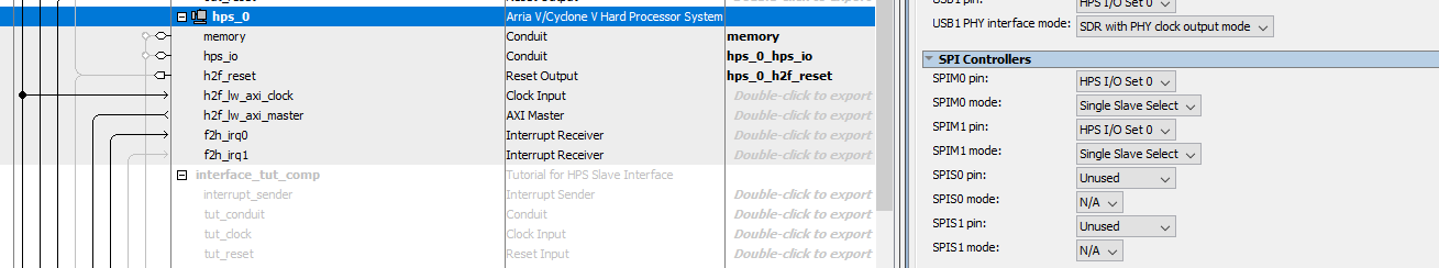
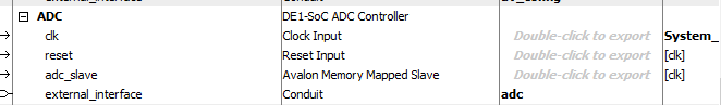
I have Linux running on a DE1-SOC and all the peripherals are working fine, except for the SPI which connect to the onboard ADC.

{

model = “Terasic DE1-SoC”;

compatible = “altr,socfpga-cyclone5”, “altr,socfpga”;

chosen {

bootargs = “console=ttyS0,115200”;

};

memory {

name = “memory”;

device_type = “memory”;

reg = <0x0 0x40000000>; /* 1GB */

};

aliases {

/* this allow the ethaddr uboot environmnet variable contents

  • to be added to the gmac1 device tree blob.

*/

ethernet0 = &gmac1;

};

leds {

compatible = “gpio-leds”;

user {

label = “user-led”;

gpios = <&gpio1 24 0>;

linux,default-trigger = “heartbeat”;

};

#if 0

/* Always-on to enable HPS i2c */

/* The alternative is to model it as a regulator for codec */

i2c0mux {

label = “i2c0-mux”;

gpios = <&gpio1 19 0>;

linux,default-trigger = “default-on”;

};

#endif

};

gpio_keys {

compatible = “gpio-keys”;

#address-cells = <1>;

#size-cells = <0>;

user_pb {

label = “user_pb”;

gpios = <&gpio1 25 0>;

linux,code = <28>;

gpio-key,wakeup;

};

};

soc {

gpio@ff708000 {

status = “okay”;

};

gpio@ff709000 {

status = “okay”;

};

gpio@ff70a000 {

status = “okay”;

};

};

sound {

compatible = “opencores,de1soc-wm8731-audio”;

i2s-controller = <&i2s>;

audio-codec = <&codec>;

i2c-mux-gpio = <&gpio1 19 0>;

};

clk48: clk48 {

compatible = “fixed-clock”;

#clock-cells = <0>;

clock-frequency = <24576000>;

clock-output-names = “clk48”;

};

clk44: clk44 {

compatible = “fixed-clock”;

#clock-cells = <0>;

clock-frequency = <33868800>;

clock-output-names = “clk44”;

};

i2s: i2s@0 {

#sound-dai-cells = <1>;

compatible = “opencores,i2s”;

reg = <0xff200000 0x20>, <0xff200020 0x20>;

clocks = <&clk44>, <&clk48>;

clock-names = “clk44”, “clk48”;

dmas = <&pdma 0>, <&pdma 1>;

dma-names = “tx”, “rx”;

};

#if 0

seg7@20 {

compatible = “dummy”;

reg = <0xff200020 0x20>;

};

vip2@100 {

compatible = “altr,vip-frame-reader-13.0”, “altr,vip-frame-reader-9.1”;

reg = <0xff200100 0x180>;

max-width = <0x400>;

max-height = <0x300>;

mem-word-width = <0x80>;

bits-per-color = <0x8>;

};

#endif

sysid@2000 {

compatible = “altr,sysid-1.0”;

reg = <0xff202000 0x8>;

};

#if 0

led_pio@10040 {

compatible = “altr,pio-1.0”;

reg = <0xff210040 0x10>;

altr,gpio-bank-width = <10>;

#gpio-cells = <1>;

gpio-controller;

};

dipsw_pio@10080 {

compatible = “altr,pio-1.0”;

reg = <0xff210080 0x10>;

interrupts = <0 42 4>;

altr,gpio-bank-width = <10>;

altr,interrupt_type = <IRQ_TYPE_EDGE_BOTH>;

#gpio-cells = <1>;

gpio-controller;

#interrupt-cells = <1>;

interrupt-controller;

};

button_pio@100c0 {

compatible = “altr,pio-1.0”;

reg = <0xff2100c0 0x10>;

interrupts = <0 41 4>;

altr,gpio-bank-width = <4>;

altr,interrupt_type = <IRQ_TYPE_EDGE_FALLING>;

#gpio-cells = <1>;

gpio-controller;

#interrupt-cells = <1>;

interrupt-controller;

};

jtag_uart@20000 {

compatible = “altr,juart-1.0”;

reg = <0xff220000 0x8>;

interrupts = <0 40 4>;

};

/*

fpgadma: fifo {

#address-cells = <1>;

#size-cells = <1>;

compatible = “altr,fpga-dma”;

reg = <0xff200060 0x20>, <0xc0001000 0x10>;

reg-names = “csr”, “data”;

dmas = <&pdma 2 &pdma 3>;

dma-names = “tx”, “rx”;

};

*/

#endif

};

&osc1 {

clock-frequency = <25000000>;

};

&gmac1 {

status = “okay”;

phy-mode = “rgmii”;

rxd0-skew-ps = <0>;

rxd1-skew-ps = <0>;

rxd2-skew-ps = <0>;

rxd3-skew-ps = <0>;

txen-skew-ps = <0>;

txc-skew-ps = <2600>;

rxdv-skew-ps = <0>;

rxc-skew-ps = <2000>;

};

&usb1 {

status = “okay”;

};

&mmc {

status = “okay”;

num-slots = <0x1>;

supports-highspeed;

broken-cd;

altr,dw-mshc-ciu-div = <0x3>;

altr,dw-mshc-sdr-timing = <0x0 0x3>;

slot@0 {

reg = <0x0>;

bus-width = <0x4>;

};

};

&i2c0 {

status = “okay”;

clock-frequency = <100000>;

speed-mode = <0>;

codec: wm8731@34 {

#sound-dai-cells = <0>;

compatible = “wlf,wm8731”;

reg = <0x1a>;

};

adxl345@53 {

compatible = “adi,adxl34x”;

reg = <0x53>;

interrupt-parent = <&gpio2>;

interrupts = <3 4>;

};

};

How would I go about adding an entry for the SPI so that Linux recognizes it automatically (/dev/spidev/) and could access the SPI peripherals (like the onboard ADC) in userspace?

I don’t see any SPI-Component in your Devicetree.
I generate Devicetree from Qsys .sopcinfo - File.
Do you use an HPS-Interface SPI or do you use an SPI - Component in Platform Desigener (Qsys) ?
If you use HPS SPI, Devicetree could look like this one:
hps_0_spim1: spi@0xfff01000 {
compatible = “snps,dw-spi-mmio-18.0”, “snps,dw-spi-mmio”, “snps,dw-apb-ssi”;
reg = <0xfff01000 0x00000100>;
interrupt-parent = <&hps_0_arm_gic_0>;
interrupts = <0 155 4>;
clocks = <&spi_m_clk>;
#address-cells = <1>; /* embeddedsw.dts.params.#address-cells type NUMBER /
#size-cells = <0>; /
embeddedsw.dts.params.#size-cells type NUMBER /
bus-num = <0>; /
embeddedsw.dts.params.bus-num type NUMBER /
num-chipselect = <4>; /
embeddedsw.dts.params.num-chipselect type NUMBER /
status = “okay”; /
embeddedsw.dts.params.status type STRING */

		spidev1: spidev@0 {
			compatible = "rohm,dh2228fv";	/* appended from boardinfo */
			reg = <0>;	/* appended from boardinfo */
			spi-max-frequency = <100000000>;	/* appended from boardinfo */
			enable-dma = <1>;	/* appended from boardinfo */
		}; //end spidev@0 (spidev1)
	}; //end spi@0xfff01000 (hps_0_spim1)

If you add HPS-SPI in Qsys-HPS-Configuration yourself, don’t forget to generate new “preloader-mkpimage.bin” and “u-boot.img”.

Thanks for the reply. What I’m trying to do is get the onboard ADC on the DE1-SoC to work in my HPS system. I initially though that the it was because of the SPI not being in the .dtb. I finally found the dts files for the board (University IP Catalog) which includes all the peripherals, including the DE1-SOC_Avalon_Up_ADC module; however, after I convert it to a dtb (using dtc) and load it in my boot sector, replacing the other dtb file, my Linux won’t boot.

So you’re saying that if I heavily modify my .dtb file, then you have to also update the uboot image and preloader? Do you also have to update the .rbf file (which is in the same folder as the .dtb and uboot)? How do I change the uboot image and preloader to be consistent with a newer .dtb file?

Best regard,
Danny

When I get home, I will upload the working .dts file (which came with the Linux image on the Terasic De1-Soc website page) and then compare it to the .dts file, which came with the University IP Catalog. Basically, I want the University Catalog .dts file to be used because it includes ALL the peripherals, including the onboard ADC.

Also, the Uni IP Catalog also comes with a pre-loaded Linux Angstrom image, but when I burn it to the micro SD card, it won’t boot anything on my board :frowning:

So, I’m using Ubuntu 16.04 with the linux-socfpga kernel, and the dts file which comes with this image is more of a generic Cyclone V .dts (and is actually name DE0-Atlas).

I hope this makes sense…

Ok. I would like to be more clear about what I’m trying to accomplish, so I’ll give you the step of what I did:

(1) Downloaded the Ubuntu 16 (Linux 4.5 Kernel) from the De1-Soc.terasic.com website and burned it to micro SD card.

(2) The dts file which this particular installation comes with is for a model (DE0-Atlas) board, and therefore is missing some of the peripherals only found on the DE1-SoC, e.g. the onboard ADC (which is what I am trying to get working in Linux using HAL (Hardware Abstraction Layer) and some simple C-code).

(3) The University Program IP Catalog comes with a Qsys file for the “DE1-SoC Computer”, which includes all the peripherals, so I generated the sopcinfo file and converted it to a .dts, and then I converted this .dts file to the .dtb file using the device tree compiler.

(4) I uploaded the new .dtb file to the Ubuntu 16 (Linux Kernel 4.5) and no go… :frowning:

So I guess my question is: what do I do from here? You mentioned that the preloader and uboot would have to be regenerated? The following files are stored in /media/ubuntu/5459-A1D6/:

socfpga.dtb
soc_system.rbf
System\ Volume\ Information
u-boot.src
zImage

I was just changing and modifying the .dtb file. Does the zImage have to also be regenerated? I read somewhere that the board’s .xml file has to be modified as well to target the particular Linux kernel I’m running.

I’m a little lost at this point, so any help would be greatly appreciated. (Been working on this for the past week or so, and feel like I’m pretty darn close to getting this thing to work.)

(1) Here is the .dts file that comes with the Ubuntu 16 (Linux 4.5 kernel) (which works -i.e. I get USB, ethernet and even some I2C action).

(2) And here is the one that I generated using the “DE1-SoC Computer” files from the Quartus 14.1 University IP Catalog.

But when I just convert (2) to .dtb and upload to SD (That has the Ubuntu 16 4.5 kernel installation) it doesn’t work (black screen, won’t boot, etc…).

Check if ADC is realy connect in HDL-Design-Toplevel.
Do you use HPS-SPI to connect to ADC (see attached picture)?
You must see hps_0_spim0 or hps_0_spim1 in Devicetree
When yes, Preloader has to configure SPI-HPS I/O Pins.
So it is better to copy new Preloader to SD-Card.
How to do this is discribet on rocketboards websites.
The most probable reason for not Booting is a mistake in Devicetree.
Compare Devicetree which is working with Devicetree which causes Boot Failure.
Do test and Comment out or add pieces of text.

Hello,
Altera’s “Univeristy IP Catalog” comes with the “DE1-SoC Computer” and has a built-in ADC module called, “DE1-SoC ADC Controller”, which shows up in Qsys as this:

Capture

I generated the new u-boot.img and preloader-mkpimage.bin files using the EoS Embedded Shell and the BSP Editor (make & make uboot).

So now, I have all new files:

(1) soc_system.rbf (which was converted from the “de1-soc Computer” .soc file)
(2) socfpga.dtb (which was converted from the sopcinfo file using the sopc2dtb function)
(3) u-boot.img (generated by BSP editor)
(4) preloader-mkpimage.bin (also generated by BSP editor)

For the first two files (soc_system.rbf, socfpga.dtb) -those can be just copied and pasted into the boot folder, correct?

I’m having trouble finding the documentation on how to replace the uboot and preloader on the SD card. The uboot file on the SD card is u-boot.src, but the one that the editor generated was u-boot.img (it looks like it also generated: u-boot, u-boot.bin, u-boot.lds, u-boot.map and u-boot.srec as well). Is the u-boot.srec what I need to replace the u-boot.src?

Do you have the link that shows how to do this?

I tried replacing the files (although I didn’t have the u-boot.scr file, and don’t know how to generate that).

I think the best thing to do is to just build the entire thing from scratch, instead of starting with that Ubuntu 16 installation, and modifying the .dtb and u-boot files.

Who would’ve thought that doing this would be so difficult?