Target is based on Cyclone V SoC. Linux version is 4.1.33. Micron SPI NOR serial EEPROM (Micron, MT128QL128ABA) flash is connected to the SPI 1 controller of the HPS. Linux probe is failing with unrecognised Id FF FF FF.
Bootlog:
-----------
[ 7.325454] m25p80 spi32766.1: unrecognized JEDEC id bytes: ff, ff, ff
[ 7.403808] m25p80: probe of spi32766.1 failed with error -2
DTS Entries:
_**spi1: spi@fff01000 { ==>snippet from socfpga.dtsi**_
** compatible = “snps,dw-apb-ssi”;**
** #address-cells = <1>;**
** #size-cells = <0>;**
** reg = <0xfff01000 0x1000>;**
** interrupts = <0 155 4>;**
** num-cs = <4>;**
** tx-dma-channel = <&pdma 20>;**
** rx-dma-channel = <&pdma 21>;**
** clocks = <&per_base_clk>;**
** status = “disabled”;**
** };**
&spi1 { //snippet from our target DTS
** status = “okay”; // snps,dw-apb-ssi**
** cfpgaSeepromr0: eeprom@0 {**
** reg = <1>;**
** compatible = “n25q128a13”, “jedec,spi-nor”;**
** /* compatible = “jedec,spi-nor”; */**
** spi-max-frequency = <54000000>;**
** #address-cells = <1>;**
** #size-cells = <1>;**
** spi-cpol;**
** spi-cpha;**
** partition@0 {**
** /* 16MB for raw data. */**
** label = “CFPGA Image”;**
** reg = <0x0 0x01000000>;**
** };**
** };**
};
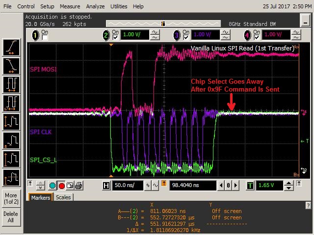
When the SPI bus is scoped, we find that the Chip Select is going away soon after the transfer (command: 9F) is sent. Attached the scope output. Do we need have the SPI Controller in some specific configuration to have the CS held low?
Please help.
regards
Mahesh
The same thing has happened.
It solved by the following method.
Perform CS control by GPIO controller.
—vv exsample dts vv—
&spi1{
compatible = “snps,dw-spi-mmio-17.0”, “snps,dw-spi-mmio”, “snps,dw-apb-ssi”;
~~~~~~~~~~~~~~~~~~~~~~~~~~~~~~~~~~~~~~~~~~~~~~~~
~~~~~~~~~~~~~~~~~~~~~~~~~~~~~~~~~~~~~~~~~~~~~~~~
cs-gpios = <&pio_0 0 0>; /* appended from boardinfo /
~~~~~~~~~~~~~~~~~~~~~~~~~~~~~~~~~~~~~~~~~~~~~~~~
~~~~~~~~~~~~~~~~~~~~~~~~~~~~~~~~~~~~~~~~~~~~~~~~
eeprom1: at25@0 {
compatible = “atmel,at25”, “st,m95256”; / appended from boardinfo */
~~~~~~~~~~~~~~~~~~~~~~~~~~~~~~~~~~~~~~~~~~~~~~~~
~~~~~~~~~~~~~~~~~~~~~~~~~~~~~~~~~~~~~~~~~~~~~~~~
}; //end at25@0 (eeprom1)
};
Thank you, Appreciate your help.
We have modified our designs to use additional GPIOs to control the CS. I don’t see the SPI devices enumerated in the system file system. Following is the dts tree. We have two slave devices on the SPI1 controller. THe probe is failing with EPROBE_DEFER (-517) error. Looks like the spi-dw-mmio.c::spi-dw-mmio-probe():of_get_named_gpio() function is returning incorrect values (though the function is successful). Any ideas on what is wrong with the below dts?
&gpio2 {
status = “okay”;
#gpio-cells = <2>;
};
&spi1 {
status = “okay”;
spi-cpha;
spi-cpol;
num-cs = <2>;
/*
* <&gpioChip gpioPinOffset ACTIVE_HIGH(0)/ACTIVE_LOW(1)
* gpioChip = gpio2
* gpioPinOffset for CS0 is 66, which is offset 8 in gpio2
* gpioPinOffset for CS1 is 62, which is offset 4 in gpio2
* ACTIVE_HIGH = 0
* ACTIVE_LOW = 1
*/
cs-gpios = <&gpio2 8 1>, <&gpio2 4 1>;
mram0: eeprom@0 {
reg = <0>;
compatible = "mr25h40";
spi-max-frequency = <50000000>;
#address-cells = <1>;
#size-cells = <1>;
spi-cpol;
spi-cpha;
partition@0 {
    /* 512KB */
    label = "MRAM Partition";
    reg = <0x0 0x80000>;
    };
};
cfpgaSeeprom0: eeprom@1 {
    reg = <1>;
    compatible = "n25q128a13", "jedec,spi-nor";
    /* compatible = “jedec,spi-nor”; */
    spi-max-frequency = <54000000>;
    #address-cells = <1>;
    #size-cells = <1>;
    spi-cpol;
    spi-cpha;
    partition@0 {
        /* 16MB for raw data. */
        label = "CFPGA Image";
        reg = <0x0 0x01000000>;
    };
};
The device I am using is Arria 10soc.
The kernel version is the same.(Linux version is 4.1.33-ltsi)
I downloaded it from RocketBoards.org.
The Linux driver of the GPIO controller included in HPS is the same.
If you are using the DTS file included in the kernel souce code tree, please refer to the following.
A different parameter in gpio definition is “gpio-controller;”
Please fix the following.
&gpio2 {
status = “okay”;
#gpio-cells = <2>;
gpio-controller; <=Add
};
Have you generated a dts file from. Socpcinfo using SOCEDS’s embedded command shell?
Hi
Thank you for the quick response. Appreciate it.
Our board is based on Cyclone V. I am using the DTS files included in the kernel source. It is not generatd using socpcinfo.
Also, I noticed that the moment I add the gpio details, the spi-dw-mmio driver is initialized/probing the device. We want to have the device accessed as MTD partitions. How to force this?
Mahesh
I have not added flash memory to the SPI interface, so I do not know.
With the following command, it is possible to check the mtd partition.
cat /proc/mtd
For the flash memory added to the qspi interface, I know the write method, but I do not know about the flash memory added to the spi interface.
https://rocketboards.org/foswiki/Documentation/GSRD131QspiProgram#Programming_QSPI_Flash_from_Linux_Console
Please investigate and tell me when you know the method.
Information on other Internet sites is shown below.
I hope it will be helpful.
●Testing using flashcp
#/*
#SPI flash testing with flashcp
#/
#To know MTD partion(partitions) is(are) present and size of partition(partitions)in flash
cat /proc/mtd
dev: size erasesize name
mtd0: 00100000 00001000 “spi-flash”
#Creating a file to be written to the flash
dd if=/dev/urandom of=./sample.bin bs=1024 count=900
900+0 records in
900+0 records out
921600 bytes (900.0KB) copied, 0.706526 seconds, 1.2MB/s
#Write the file to the partition - this erases the partition, writes the file and verifies
flashcp -v ./smaple.bin /dev/mtd0
Erasing block: 225/225 (100%)
Writing kb: 896/900 (99%)
Verifying kb: 896/900 (99%)
●Testing using jffs2
#/*
#SPI flash testing with jffs2
#/
#Erase a the whole partition with jffs2 markers
flash_eraseall -j /dev/mtd0
Erasing 4 Kibyte @ ff000 - 97% complete. Cleanmarker written at ff0000.
Erasing 4 Kibyte @ 100000 - 100% complete
#create a directory
mkdir spi_flash0
#Mount the partition to spi_flash0
mount -t jffs2 /dev/mtdblock0 /spi_flash0
#Creating a file to be written to the flash
dd if=/dev/urandom of=./sample.bin bs=1024 count=900
900+0 records in
900+0 records out
921600 bytes (900.0KB) copied, 0.706526 seconds, 1.2MB/s
#Write the file to the flash
cp ./sample.bin /spi_flash0/
#Check the presence of the file(s) in spi_flash0
ls /spi_flash0
sample.bin
#Unmount
umount spi_flash0
#Mount again - MTD 0 to spi_flash0
mount -t jffs2 /dev/mtdblock0 /spi_flash0
#Compare the files - there should be no differences
diff ./sample.bin /spi_flash0/sample.bin
#Unmount
umount spi_flash0
#The data can be verified again after a power on reset if desired.
Expected Output
jffs2 log:
#flash_eraseall -j /dev/mtd0
Erasing 4 Kibyte @ ff000 - 97% complete. Cleanmarker written at ff0000.
Erasing 4 Kibyte @ 100000 - 100% complete
#mkdir spi_flash0
#mount -t jffs2 /dev/mtdblock0 /spi_flash0
#dd if=/dev/urandom of=./sample.bin bs=1024 count=900
900+0 records in
900+0 records out
921600 bytes (900.0KB) copied, 0.706526 seconds, 1.2MB/s
#cp ./sample.bin /spi_flash0/
#ls /spi_flash0
sample.bin
#umount spi_flash0
#mount -t jffs2 /dev/mtdblock0 /spi_flash0
#diff ./sample.bin /spi_flash0/sample.bin
