Cyclone V Device Tree Configuration

Greeting everyone! I am relatively new to this forum (but not rocketboard wiki), and if this is common question, feel free to send me a link that answers my question, thank you :slight_smile:

For reference, I am running 4.14.30 Linux kernel.

I am currently working with Cyclone V socfpga using IoTOctopus board. I am attempting to configure a basic device tree to communicate with a soft IP UART module on FPGA fabric. There are two resources that are useful that Iā€™ve found: How to create a device tree (Rocketboard) and the official kernel docs about FPGA interface peripherals here.

For record, Iā€™ve attempted to implement a device tree overlay based on RocketBoard page, but Iā€™ve had trouble as up on applying the probe fails with error -22, which is either maxed out number of ports or incorrect memory location (later seems likely). I am trying to remedy my confusion to solve this problem.

Q1. What is the exact meaning of ā€˜rangesā€™ in in relation to child nodes?
image
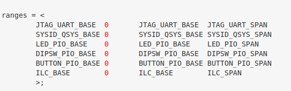
I understand that ranges can be used to remap from one address region to another. In that case how come each entry of begin with the absolute address of the peripheral and not the bridge itself? I figured that it may be that the bus address is set using chip select of 0, but then where are the address ranges for buses themselves are configured?

Q2. Does anyone have experience using partial reconfigure device tree options?
The kernel docs indicate that it is possible to use device tree overlays to allow automatic reprogramming of the FPGA fabric, either partially or fully. Does anyone have advice on how to implement that (or at least helpful links)? There is info about it in kernel docs, but once again I am uncertain about the validity of those solutions.

Q3. Why are the configurations from Rocketboard and the kernel docs different?
In kernel docs, the fpga region is a child node to fpga bridge, which makes sense to me, given that a peripheral is tied to specific bus. However socfpga.dtsi defines fpga bridge and base region parallel to each other (which I assume is the correct way). Does anyone know what is the difference ?

Thank you so much!

Sorry if these are dumb questions, but this is the first thing that comes to mind.

  1. How are the ARMs actually going to talk to your UART? Is it connected over one of the AXI busses from the HPS? I am not familiar with all of the HPS-FPGA connections. Are there non-AXI ones? Iā€™ll take a look at the TRM, but I was wondering if you knew off-hand
  2. Can you find the kernel source code for the driver that is probing and failing? If you post your entire device tree, I could take a look. You probably know this, but you can look at the ā€œcompatibleā€ tag and map that to the kernel software.
  3. Do you have a way SignalTap whatever bus the HPS is using to talk to the UART? This should give you a good idea if the hardware is right. You yourself said that the error could indicated incorrect memory location. This should give you a hint.

I would try using this device tree, which I have had success with (albeit with a newer kernel)

with the addition of whatever the UART is supposed to look like wherever it is supposed to be (I think you said under FPGA manager node).

Q1. What is the exact meaning of ā€˜rangesā€™ in in relation to child nodes?
I have no idea. Sorry
Q2. Does anyone have experience using partial reconfigure device tree options?
Yes. If you use my device tree above, FPGA manager should come up in sysfs. From there you should be able to reprogram FPGA following this guide.


Q3. Why are the configurations from Rocketboard and the kernel docs different?
Not sure. Any reason you are not choosing to use Intelā€™s socfpga kernel?

I donā€™t have a ton of experience with device trees and the kernel compatibility Intel offers, but maybe this can give you a start. I will take a peak through the reference device tree listed above. I think it is fairly bold to attempt to build a device tree from scratch. I would try to adapt and existing one to the layout of your board. I think a fair bit of stuff in the reference device tree is just to configure hard peripherals on the chip. There is no reason to reinvent the wheel there.

I am not sure how good this tool is, but maybe it could be of use. It might be able to automate what you are trying to do (unless the purpose is to write the device tree manually as an exercise)

Greetings jackfrye11, thank you for answering! To answer your question:

  1. I will be running a compiled C script which accessed UART Softcore IP using drivers provided by Altera over lwhps2fpga bus. I believe all of them are done at least partly through AXI.
  2. Yes, I have found the code. It is altera_uart and the output is error -22 which is EINVAL. Given it fails in probe function it must be either a memory issue or MAX_UART_PART issue, which I will need to check out.
  3. I suppose it would be possible, but given my issue is with Linux, I donā€™t see how SignalTap may help me.

To clarify a few other points:

  1. Iā€™m using linux-socfpga-ltsi-4.14.30 kernel.
  2. If you check documentation under the linux-socfpga kernel, the device tree in examples for FPGA Region differs to that in Rocketboard tutorial. I would preferably want to know where the difference comes from.
  3. I think I failed to make it clear that there is already a functional device tree for Linux HPS called socfpga_cyclone5.dtsi , which I understand is the stock socfgpa device tree for Cyclone V. What I am having difficulties with is writing an overlay such that it my probes would not fail up on application of this overlay.
  4. The Device Tree Generator seems outdated for my Quartus/kernel version? I prefer not to rely on automatic generation until I feel comfortable with understanding the underlying logic. I suppose it might be the only way at some point soon.

Here is my overlay:

/dts-v1/;
/plugin/; 
 
#include "IoTOctopus_QSYS.h" 
#include "dt-bindings/interrupt-controller/irq.h" 
 
/* 
 * Redefine the macros from soc_system.h into shorter macros and more useful 
 * values that we can use directly in the devicetree definition. 
 */ 
#define GPS_UART_BASE           HPS_0_ARM_A9_0_GPS_UART_BASE   // Address: 0xff200840
#define GPS_UART_SPAN           HPS_0_ARM_A9_0_GPS_UART_SPAN
#define GPS_UART_IRQ              (HPS_0_GPS_UART_IRQ  + 72 -32)

#define SPI_MASTER_BASE         HPS_0_ADC_SPI_MASTER_BASE
#define SPI_MASTER_SPAN         HPS_0_ADC_SPI_MASTER_SPAN
#define SPI_MASTER_IRQ          (HPS_0_ADC_SPI_MASTER_IRQ + 72 -32)


/ { 
fragment@0 { 
 
target-path = "/soc/base-fpga-region"; 
 
#address-cells = <0x1>; 
#size-cells = <0x1>; 
 
__overlay__ { 
 
        external-fpga-config; 
 
        #address-cells = <0x2>; 
        #size-cells = <0x1>; 

        ranges = < 
                 GPS_UART_BASE 0 GPS_UART_BASE GPS_UART_SPAN
                >; 
                
 
        GPS_UART: GPS_UART@GPS_UART_BASE,0 { 
                compatible = "altr,uart-1.0"; 
                reg = <0 GPS_UART_BASE GPS_UART_SPAN>; 
                interrupts = <0 GPS_UART_IRQ IRQ_TYPE_LEVEL_HIGH>; 
        };
 
}; // __overlay__ 
 
}; // fra

You may notice it looks very identical to the one in tutorial on how to write device tree.

Thank you for your time anyway. I may come back later and add more details once I am less tired.

Ok I read all the docs. Now I get the picture of what you are doing and why you are so confused. I have never done a lot of this so I do not know what will work. I have used overlays, but that was back in college and it was GPIO, not an FPGA device.

It sounds like if you have the right bridges enabled and you do something like this (make sure you correlated the phandles to socfpga.dtsi (at least that was where I found these nodes))

		fpga_bridge0: fpga_bridge@ff400000 {
			compatible = "altr,socfpga-lwhps2fpga-bridge";
			reg = <0xff400000 0x100000>;
			resets = <&rst LWHPS2FPGA_RESET>;
			clocks = <&l4_main_clk>;
		};

		fpga_bridge1: fpga_bridge@ff500000 {
			compatible = "altr,socfpga-hps2fpga-bridge";
			reg = <0xff500000 0x10000>;
			resets = <&rst HPS2FPGA_RESET>;
			clocks = <&l4_main_clk>;
		};

that the FPGA will actually program itself and reenable all the birdges you had enabled beforehand. See below overlay

/dts-v1/ /plugin/;
/ {
	fragment@0 {
		target = <&fpga_region0>;
		#address-cells = <1>;
		#size-cells = <1>;
		__overlay__ {
			#address-cells = <1>;
			#size-cells = <1>;

			firmware-name = "soc_system.rbf";
			fpga-bridges = <&fpga_bridge1>;
			ranges = <0x20000 0xff200000 0x100000>,
				 <0x0 0xc0000000 0x20000000>;

			gpio@10040 {
				compatible = "altr,pio-1.0";
				reg = <0x10040 0x20>;
				altr,ngpio = <4>;
				#gpio-cells = <2>;
				clocks = <2>;
				gpio-controller;
			};

			onchip-memory {
				device_type = "memory";
				compatible = "altr,onchipmem-15.1";
				reg = <0x0 0x10000>;
			};
		};
	};
};

In this case, you will just need to replace the GPIO and OCM nodes with whatever the kernel is expecting to see for ā€œaltr,uart-1.0ā€ (maybe there is an example out there somewhere or maybe you can try the DT generator tool to get a feel for what metadata should be in there).

It sounds like you went the RocketBoards guide direction. Try fitting the kernel doc stuff into socfpga.dtsi and see if that gets you anywhere. Maybe you have already gotten this far. If so, I would then try printkā€™ing the UART driver to see exactly where it is returning EINVAL.

I think that ranges stuff is just device tree lingo/syntax where ranges is some data structure that is mapped to with the reg tag, but I am not a device tree expert.

Sorry I canā€™t be more help. I would try to keep it as simple and stupid as possible, which to me would be to go the kernel doc route and mix it in with the existing cyclonev out-of-the-box trees. There seems to be a strong mapping between the kernel doc example and the stuff in socfpga.dtsi.