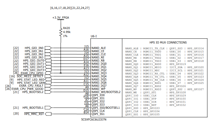
Our team has inherited a design using a Cyclone5 with the HPS and FPGA. The HPS is running Linux. We need to have Linux user space access to 8 GPIO signals - 4 in and 4 out.
The fundamental issue is that the /sys/class/gpio is populated with export and unexport devices, but there are no gpiochip or gpionnn directories here. As I understand it the gpiochip and gpio directories are needed for userspace access to GPIO when using the sysfs GPIO driver support.
It seems we have some various “parts” that are skirting around the GPIO subsystem, but they are not tying together to place the expected devices in the linux /sys/class/gpio directory. Obiously I’m missing something.
I could use some guidance on what that “something” or those “somethings” are.
Here are the pieces I’m aware of relating to GPIO in the system:
- We use Yocto to build the 4.9.0-rc3-altera kernel. Here are (I think) the important kernel config settings for GPIO:
PTP clock support
CONFIG_PTP_1588_CLOCK=y
CONFIG_DP83640_PHY is not set
CONFIG_ARCH_HAVE_CUSTOM_GPIO_H=y
CONFIG_GPIOLIB=y
CONFIG_GPIO_DEVRES=y
CONFIG_OF_GPIO=y
CONFIG_GPIOLIB_IRQCHIP=y
CONFIG_DEBUG_GPIO is not set
CONFIG_GPIO_SYSFS=y
CONFIG_GPIO_GENERIC=y
-
Additionally, the build system has a device tree file with the following GPIO entries in it (linux-udsp is the Yocto “machine” name) :
poky/meta-udsp/recipes-kernel/linux/linux-udsp/arch/arm/boot/dts/socfpga.dtsi:gpio0: gpio@ff708000 { #address-cells = <1>; #size-cells = <0>; compatible = "snps,dw-apb-gpio"; reg = <0xff708000 0x1000>; clocks = <&l4_mp_clk>; status = "disabled"; porta: gpio-controller@0 { compatible = "snps,dw-apb-gpio-port"; gpio-controller; #gpio-cells = <2>; snps,nr-gpios = <29>; reg = <0>; interrupt-controller; #interrupt-cells = <2>; interrupts = <0 164 4>; }; }; gpio1: gpio@ff709000 { #address-cells = <1>; #size-cells = <0>; compatible = "snps,dw-apb-gpio"; reg = <0xff709000 0x1000>; clocks = <&l4_mp_clk>; status = "disabled"; portb: gpio-controller@0 { compatible = "snps,dw-apb-gpio-port"; gpio-controller; #gpio-cells = <2>; snps,nr-gpios = <29>; reg = <0>; interrupt-controller; #interrupt-cells = <2>; interrupts = <0 165 4>; }; }; gpio2: gpio@ff70a000 { #address-cells = <1>; #size-cells = <0>; compatible = "snps,dw-apb-gpio"; reg = <0xff70a000 0x1000>; clocks = <&l4_mp_clk>; status = "disabled"; portc: gpio-controller@0 { compatible = "snps,dw-apb-gpio-port"; gpio-controller; #gpio-cells = <2>; snps,nr-gpios = <27>; reg = <0>; interrupt-controller; #interrupt-cells = <2>; interrupts = <0 166 4>; }; }; -
and finally, the HPS IO to MUX connections (we’re interested in using HPS_GIO_IN0 through HPS_GIO_IN3 and HPS_GIO_OUT0 through HPS_GIO_OUT3:
